Xtensa ESP32 Reversing
TLDR
This is not a write-up for any particular NSEC challenge. Instead, it is a general guide to reverse engineering the Xtensa ESP32. This block is an outline and reference guide. More details follow.
- Get esptool:
pipx install esptool- basic information:
esptool.py flash_id - read flash:
esptool.py --chip esp32 --baud 2000000 --port /dev/ttyUSB0 read_flash 0x0 0x400000 firmware-4M.bin - dump memory: above but
dump_mem, with different offsets - script to dump all segments
- basic information:
- Get esp32knife:
git clone https://github.com/BlackVS/esp32knife- produce a .elf for IDA:
python3 esp32knife/esp32knife.py --chip=esp32 load_from_file eflash.bin
- Generating FLIRT Signatures
- get previous badge
git clone https://github.com/nsec/nsec-badge - build it
- get Mandiant FLARE
git clone https://github.com/mandiant/flare-ida - open former in IDA, process, File->Script File->idb2pat.py
- get IDA FLAIR Tools
- use sigmake to convert the pat to a .sig
- get previous badge
- Missing Instructions
- IDAPython script with missing instructions, place in $IDA/plugins
- Open the .elf in IDA
- Processor: Tensilica Xtensa MCU
- disable Analysis
- script to load segments
- enable Analysis
- script to add_func unreferenced subs
- Get to work.
- GLHF
Basics / esptool
Installation:
I’ll be including full esptool outputs in this section, and they can get long, so mostly, comments will go above the code blocks they reference. In this case, this is just a note that the esptool in APT is ~4 years out of date, so you should get one from pip.
pipx install esptool
Chip Identification:
The flash_id command doesn’t need arguments, as it can figure them out itself. The most important lines of the dump below are the following:
- Chip is ESP32-D0WDQ6
- Crystal is 40MHz
- Detected flash size: 4MB
[0](Ghroth)❯ esptool.py flash_id
esptool.py v4.5.1
Found 1 serial ports
Serial port /dev/ttyUSB0
Connecting....
Detecting chip type... Unsupported detection protocol, switching and trying again...
Connecting....
Detecting chip type... ESP32
Chip is ESP32-D0WDQ6 (revision v1.0)
Features: WiFi, BT, Dual Core, 240MHz, VRef calibration in efuse, Coding Scheme None
Crystal is 40MHz
MAC: c8:f0:9e:b1:82:78
Uploading stub...
Running stub...
Stub running...
Manufacturer: 5e
Device: 4016
Detected flash size: 4MB
Hard resetting via RTS pin...
Reading out the eFuses
On the ESP32, eFuses are one-time-programmable, by writing 0->1. So, we are interested in which bits have been set. In this case, we can see that no interesting fuses have been set.
[2](Ghroth)❯ espefuse.py --chip esp32 --port --baud 115200 /dev/ttyUSB0 summary
espefuse.py v4.5.1
Connecting....

=== Run "summary" command ===
EFUSE_NAME (Block) Description  = [Meaningful Value] [Readable/Writeable] (Hex Value)
----------------------------------------------------------------------------------------
Calibration fuses:
BLK3_PART_RESERVE (BLOCK0):        BLOCK3 partially served for ADC calibration data   = False R/W (0b0)
ADC_VREF (BLOCK0):                 Voltage reference calibration                      = 1100 R/W (0b10000)

Config fuses:
XPD_SDIO_FORCE (BLOCK0):           Ignore MTDI pin (GPIO12) for VDD_SDIO on reset     = False R/W (0b0)
XPD_SDIO_REG (BLOCK0):             If XPD_SDIO_FORCE, enable VDD_SDIO reg on reset    = False R/W (0b0)
XPD_SDIO_TIEH (BLOCK0):            If XPD_SDIO_FORCE & XPD_SDIO_REG                   = 1.8V R/W (0b0)
CLK8M_FREQ (BLOCK0):               8MHz clock freq override                           = 53 R/W (0x35)
SPI_PAD_CONFIG_CLK (BLOCK0):       Override SD_CLK pad (GPIO6/SPICLK)                 = 0 R/W (0b00000)
SPI_PAD_CONFIG_Q (BLOCK0):         Override SD_DATA_0 pad (GPIO7/SPIQ)                = 0 R/W (0b00000)
SPI_PAD_CONFIG_D (BLOCK0):         Override SD_DATA_1 pad (GPIO8/SPID)                = 0 R/W (0b00000)
SPI_PAD_CONFIG_HD (BLOCK0):        Override SD_DATA_2 pad (GPIO9/SPIHD)               = 0 R/W (0b00000)
SPI_PAD_CONFIG_CS0 (BLOCK0):       Override SD_CMD pad (GPIO11/SPICS0)                = 0 R/W (0b00000)
DISABLE_SDIO_HOST (BLOCK0):        Disable SDIO host                                  = False R/W (0b0)

Efuse fuses:
WR_DIS (BLOCK0):                   Efuse write disable mask                           = 0 R/W (0x0000)
RD_DIS (BLOCK0):                   Efuse read disable mask                            = 0 R/W (0x0)
CODING_SCHEME (BLOCK0):            Efuse variable block length scheme                 = NONE (BLK1-3 len=256 bits) R/W (0b00)
KEY_STATUS (BLOCK0):               Usage of efuse block 3 (reserved)                  = False R/W (0b0)

Identity fuses:
MAC (BLOCK0):                      Factory MAC Address                                = c8:f0:9e:b1:82:78 (CRC 0xff OK) R/W
MAC_CRC (BLOCK0):                  CRC8 for factory MAC address                       = 255 R/W (0xff)
CHIP_VER_REV1 (BLOCK0):            Silicon Revision 1                                 = True R/W (0b1)
CHIP_VER_REV2 (BLOCK0):            Silicon Revision 2                                 = False R/W (0b0)
WAFER_VERSION_MINOR (BLOCK0):      WAFER VERSION MINOR                                = 0 R/W (0b00)
CHIP_PACKAGE (BLOCK0):             Chip package identifier                            = 0 R/W (0b000)
CHIP_PACKAGE_4BIT (BLOCK0):        Chip package identifier #4bit                      = 0 R/W (0b0)
MAC_VERSION (BLOCK3):              Version of the MAC field                           = 0 R/W (0x00)
WAFER_VERSION_MAJOR (BLOCK0):      calc WAFER VERSION MAJOR from CHIP_VER_REV1 and CH = 1 R/W (0b001)
                                   IP_VER_REV2 and apb_ctl_date (read only)
PKG_VERSION (BLOCK0):              calc Chip package = CHIP_PACKAGE_4BIT << 3 + CHIP_ = 0 R/W (0x0)
                                   PACKAGE (read only)

Security fuses:
FLASH_CRYPT_CNT (BLOCK0):          Flash encryption mode counter                      = 0 R/W (0b0000000)
UART_DOWNLOAD_DIS (BLOCK0):        Disable UART download mode (ESP32 rev3 only)       = False R/W (0b0)
FLASH_CRYPT_CONFIG (BLOCK0):       Flash encryption config (key tweak bits)           = 0 R/W (0x0)
CONSOLE_DEBUG_DISABLE (BLOCK0):    Disable ROM BASIC interpreter fallback             = True R/W (0b1)
ABS_DONE_0 (BLOCK0):               Secure boot V1 is enabled for bootloader image     = False R/W (0b0)
ABS_DONE_1 (BLOCK0):               Secure boot V2 is enabled for bootloader image     = False R/W (0b0)
JTAG_DISABLE (BLOCK0):             Disable JTAG                                       = False R/W (0b0)
DISABLE_DL_ENCRYPT (BLOCK0):       Disable flash encryption in UART bootloader        = False R/W (0b0)
DISABLE_DL_DECRYPT (BLOCK0):       Disable flash decryption in UART bootloader        = False R/W (0b0)
DISABLE_DL_CACHE (BLOCK0):         Disable flash cache in UART bootloader             = False R/W (0b0)
BLOCK1 (BLOCK1):                   Flash encryption key                               = 00 00 00 00 00 00 00 00 00 00 00 00 00 00 00 00 00 00 00 00 00 00 00 00 00 00 00 00 00 00 00 00 R/W
BLOCK2 (BLOCK2):                   Secure boot key                                    = 00 00 00 00 00 00 00 00 00 00 00 00 00 00 00 00 00 00 00 00 00 00 00 00 00 00 00 00 00 00 00 00 R/W
BLOCK3 (BLOCK3):                   Variable Block 3                                   = 00 00 00 00 00 00 00 00 00 00 00 00 00 00 00 00 00 00 00 00 00 00 00 00 00 00 00 00 00 00 00 00 R/W

Flash voltage (VDD_SDIO) determined by GPIO12 on reset
Firmware Dump
read_flashtakes offset, size in bytes, and filename.- this command is slow. Took over six minutes at default
--baud 115200. - ESP32 supports faster speeds,
--baud 921600, is the highest recommended. - the fastest I could run at was
--baud 2000000. It downloaded in 30.7s. I did get occasional errors at this speed. Perhaps--baud 1500000is safer.
[2](Ghroth)❯ esptool.py --chip esp32 --baud 2000000 --port /dev/ttyUSB0 read_flash 0x0 0x400000 firmware-4M.bin
esptool.py v4.5.1
Serial port /dev/ttyUSB0
Connecting....
Chip is ESP32-D0WDQ6 (revision v1.0)
Features: WiFi, BT, Dual Core, 240MHz, VRef calibration in efuse, Coding Scheme None
Crystal is 40MHz
MAC: c8:f0:9e:b1:82:78
Uploading stub...
Running stub...
Stub running...
Changing baud rate to 2000000
Changed.
4194304 (100 %)
Read 4194304 bytes at 0x00000000 in 30.7 seconds (1091.9 kbit/s)...
Hard resetting via RTS pin...
Memory Dumps
One of the many annoying things about reversing firmwares is finding the loader loop and correctly populating all the memory segments with the correct data. This can be circumvented, if we can dump RAM at runtime. However, the ESP32 doesn’t have a simple flat memory space. It’s flat, but it’s not simple.
From the ESP32 Technical Reference Manual:
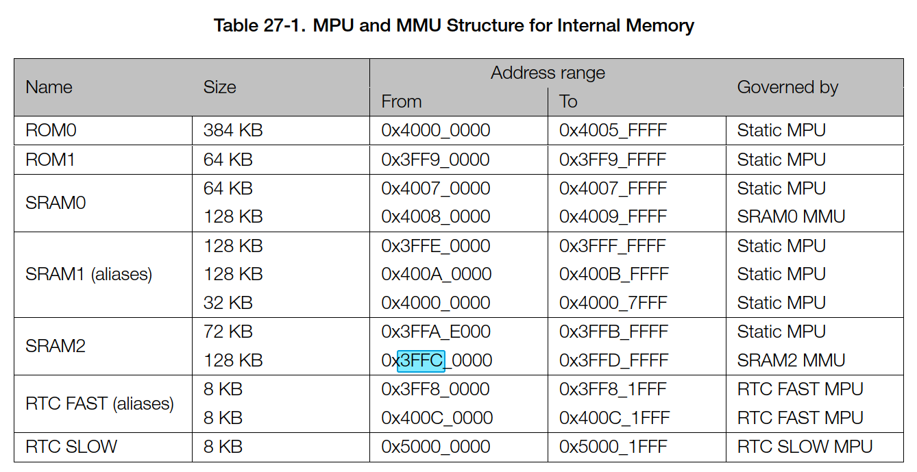
Now, it’s easy enough to dump the ROM segments and some of the RAM segments, but some of them are only populated by the runtime, and esptool.py dump_mem will reset the board into the bootloader in order to do the downloads. I had particular problems with SRAM2. A friend used JTAG to grab that segment for me. YMMV. The general form of the command is:
[0](Ghroth)❯ esptool.py --chip esp32 --baud 115200 --port /dev/ttyUSB0 dump_mem $((0x4000_0000)) $((0x4006_0000-0x4000_0000)) irom0.bin
I am providing a shell script to dump all the memory segments I could identify:
dumpSegments.sh
#!/bin/zsh

CHIP=esp32
BAUD=1500000
PORT=/dev/ttyUSB0

# Read Out Flash
PREFIX="esptool.py --chip ${CHIP} --baud ${BAUD} --port ${PORT} read_flash"
for SEG START END in                 \
    eflash      0x0         0x400000 \
; do
    echo
    echo dumping ${SEG}
    ${PREFIX} ${START} $(($END-$START+1)) ${SEG}.bin
done

# Dump Memory Segments
PREFIX="esptool.py --chip ${CHIP} --baud ${BAUD} --port ${PORT} dump_mem"
for SEG START END in                   \
    irom0       0x40000000  0x4005FFFF \
    irom1       0x3FF90000  0x3FF9FFFF \
    sram0-0     0x40070000  0x4007FFFF \
    sram0-1     0x40080000  0x4009FFFF \
    sram1-0     0x3FFE0000  0x3FFFFFFF \
    sram1-1     0x400A0000  0x400BFFFF \
    sram2       0x3FFAE000  0x3FFDFFFF \
    rtc-fast-0  0x3FF80000  0x3FF81FFF \
    rtc-fast-1  0x400C0000  0x400C1FFF \
    rtc-slow    0x50000000  0x50001FFF \
; do
    echo
    echo dumping ${SEG}
    ${PREFIX} ${START} $(($END-$START+1)) ${SEG}.bin
done
Once you’ve got them all, you need to add them to IDA. Manually, this is done with File->Load file->Additional binary file…, followed by Segments->Edit Segment->…, but that’s a lot of work. Instead, we could spend way more time browsing the IDAPython documentation and write a script to do it (use with File->Script File).
addSegments.py
Segments = [
        # ["eflash-0", 0x3F400000, 0x3F7FFFFF, 4], # already mapped: .flash.rodata
        # ["eram",     0x3F800000, 0x3FBFFFFF, 6], # large and low value for me
        ["peripheral", 0x3FF00000, 0x3FF7FFFF, 6], # memory-mapped IO
        ["irom1",      0x3FF90000, 0x3FF9FFFF, 4], # map manually
        ["sram2",      0x3FFAE000, 0x3FFDFFFF, 6], # re-map
        ["sram1-0",    0x3FFE0000, 0x3FFFFFFF, 6], # map manually
        ["irom0",      0x40000000, 0x4005FFFF, 5], # map manually
        ["sram0-0",    0x40070000, 0x4007FFFF, 7], # map manually
        # ["sram0-1",  0x40080000, 0x4009FFFF, 7], # already mapped: .iram.vectors
        ["sram1-1",    0x400A0000, 0x400BFFFF, 7], # map manually
        # ["eflash-1", 0x400C2000, 0x40BFFFFF, 5], # already mapped: .flash.text is a subset of this
        ]

def loadBinaryFile(segment):
    name,start,end,perm = segment
    filename = name + ".bin"
    # load segment
    flags = ida_loader.NEF_SEGS
    if start >= 0x40000000:
        flags |= ida_loader.NEF_CODE
    li = ida_diskio.open_linput(filename, False)
    if li:
        ida_loader.load_binary_file(filename, li, flags, 0, 0, start, 0)
    else:
        print("Warning: Could not load "+filename)
        return False
    # fix segment attributes
    seg = ida_segment.getseg(start)
    if seg:
        if start >= 0x40000000:
            seg.align = 5 # dword
            ida_segment.set_segm_class(seg, "CODE", SEG_CODE)
        else:
            seg.align = 1 # byte
            ida_segment.set_segm_class(seg, "DATA", SEG_DATA)
        seg.perm = perm
        ida_segment.set_segm_name(seg, "."+name, 0)
    else:
        print("Warning: Segment "+name+" not created.")
        return False
    return True

for segment in Segments:
    if segment[0] == "peripheral":
        name,start,end,perm = segment
        ida_segment.add_segm(0, start, end, "."+name, "DATA", SEG_DATA)
        seg = ida_segment.getseg(start)
        seg.perm = 6
        seg.align = 6 # 4KB
    else:
        loadBinaryFile(segment)
Reverse Engineering
FLAIR Signatures
The NorthSec CTF Team kindly posted the sources for their 2021 North Sectoria “Horsey” badge. There are installation/build instructions, but they don’t quite work for me. Something about Python 3.11 incompatibility. I fixed by updating the submodule to “v4.4.5” instead of a pinned commit.
Do NOT accidentally flash the Tie badge with the Horsey firmware.
Once it’s built (crossed-fingers), ida64 ./build/nsec-esp32.elf and let it process. Then get idb2pat from github:Mandiant FLARE, and File->Script File->idb2pat.py, then save the result.
At this point you should use sigmake to convert the .pat file into a .sig file, which is reasonably well documented elsewhere. Also, I don’t have an up-to-date copy of the IDA SDK, so I can’t do it myself. :(
Missing Instructions
The Xtensa MCU module that IDA 8.0 has doesn’t disassemble all the instructions on this badge, so we’re going to need to extend it. There is a great article on this by Anton@Apriorit: Adding instructions to the IDA processor module with a new plugin.
However, it’s still missing a couple instructions. For example, the following.
.flash.text:40102950                 .byte 0x3D ; =
.flash.text:40102951                 .byte 0xF0
An easy way to find out what’s missing is to use gcc/objdump. I found this method in a useful stackexchange comment. Consider the following:
opcode.c
const char *input = "\x3d\xf0";
int main () { return 0; }
[0](celeano)❯ xtensa-esp32-elf-gcc -g -c opcode.c
[0](celeano)❯ xtensa-esp32-elf-objdump --disassemble-all --section=.rodata -M intel opcode.o
opcode.o:     file format elf32-xtensa-le

Disassembly of section .rodata:
00000000 <.rodata>:
   0:   f03d            nop.n
        ...
Apparently 3d f0 is a 2-byte NOP (the .n indicates two byte instructions).
Using methods like this and by referencing the official Xtensa ISA, we can build a python plugin that decodes all the instructions we need. I’ve written a module with 47 missing or incomplete instructions, which helps IDA greatly: IDAPython script with missing instructions. Place it in $IDA/plugins.
Unreferenced Subroutines
However, many subroutines are still unreferenced. Fortunately, most (possibly even all) functions begin with a entry a1 0x?0 opcode. This is bytes 36 ?1 0?. Unfortunately, IDA doesn’t let us search for nibble-strings, so we need to search for 0x36 and filter down the results. BIN_SEARCH_BITMASK would be really useful here, if it worked with bin_search().
createFunctions.py
ea = 0x0
counter = 0
failures = 0
print("STARTING STARTING STARTING")
while True:
    ea = ida_bytes.find_byte(ea+1,0xffffffff, 0x36, 0)
    if ea == BADADDR:
        break
    buf = get_bytes(ea,3)
    if (buf[0]&0xFF) != 0x36 or (buf[1]&0x0F) != 0x01 or (buf[2]&0xF0) != 0x00:
        continue
    if buf == b'\x36\x01\x00':
        continue # would be `entry a1,0`, which doesn't happen
    if ida_funcs.get_func(ea):
        continue # already a function here
    mnem = ida_ua.ua_mnem(ea) or ida_ua.ua_mnem(ea-1) or ida_ua.ua_mnem(ea-2)
    if mnem and mnem != 'entry':
        continue
    if is_data(ida_bytes.get_flags(get_item_head(ea))):
        del_items(ea)
    r = add_func(ea)
    if r:
        counter += 1
    else:
        failures += 1
    print("Creating: "+hex(ea)+" => "+str(r))
print("Created %d/%d new functions."%(counter,counter+failures))
Conclusion
Hopefully, all this combined will get you from “what do I do with this badge” to searching strings, following XRefs, and figuring out functions quickly and efficiently.